Networking
- Informational SOP Template - DO NOT USE
- SD-WAN - A Cloud-focused WAN routing technique
- How to factory reset a Cisco Meraki switch
- The OSI model and the basics of network troubleshooting
- How a network switch works
- How a router works
- How OSPF works
- How IS-IS works
- How BGP works
- MPLS - A WAN routing technique
Informational SOP Template - DO NOT USE
| Author |
Date |
Revision |
| Author |
04/18/2024 | 1.0 |
| Related product (if any): |
N/A |
| Description: | N/A |
| Notes: |
N/A |
| Files Needed: |
N/A |
| Information: | N/A |
SD-WAN - A Cloud-focused WAN routing technique
| Author |
Date |
Revision |
| Samuel Knoppe |
04/23/2024 | 1.4 |
| Related product (if any): |
N/A |
| Description: | Describes SD-WAN and what it's used for. |
| Notes: |
Knowledge of dynamic routing protocols, MPLS and WAN concepts, and the OSI Model will prove useful. |
| Files Needed: |
N/A |
| Information: |
What is SD-WAN? Software-Defined Wide Area Networking (SD-WAN) architecture uses a centralized control function to steer traffic securely and intelligently across the WAN and directly to trusted SaaS and IaaS providers. This provides a more seamless experience and reduces costs for maintaining a more traditional WAN infrastructure, but the primary benefit is the enabled use of SaaS and IaaS services across the WAN. This is something like a traditional MPLS infrastructure cannot do natively with causing extra configuration and overhead.
Traditional WANs based on conventional routers weren't designed with the cloud in mind, and typically backhauled all traffic, including cloud-destined traffic, from branch offices to a hub or data center where advanced security inspection services can be applied. This delay caused by backhaul impairs application performance, resulting in poor user experience.
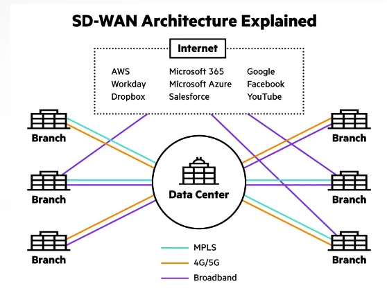
The SD-WAN model seeks to designed an architecture which fully supports applications hosted in on-premises data centers, public or private clouds, and SaaS services like Microsoft 365, Workday, Dropbox, and more. It supports these by providing the highest levels of performance.
How does SD-WAN work? Traditional conventional router-centric models for WAN distributes control functions across all devices in the network and simply routes traffic based on TCP/IP addresses and ACLs. This traditional model is rigid, complex, inefficient, and not cloud-friendly resulting in a suboptimal user experience.
SD-WAN is intended to deliver a superior application quality of experience (QoEx) for users. By identifying applications, an SD-WAN provides intelligent application-aware routing across the WAN. Each class of applications receives the appropriate QoS and security policy enforcement, all in accordance with business needs. Secure local internet breakout of IaaS and SaaS application traffic from the branch provides the highest levels of cloud performance while protecting the enterprise from threats.
The networking-specifics of SD-WAN and its functionality are beyond the scope of this surface-level document, but it utilizes tunnels and routing protocols across various mediums in order to securely deliver traffic to the endpoints from the cloud. The rollout and deployment of this architecture is handled through the cloud WAN configuration page.
SD-WAN vs. MPLS The main gist of MPLS is that it is a common method for constructing the connections between LANs that make up wide area networks (WANs). MPLS uses specialized routers which are able to send and receive MPLS packets along predetermined paths, improving upon the typical way the Internet works. These predetermined network paths can be used as the connective tissue that comprises a WAN and allow multiple virtual WANs to coexist over a shared network backbone. However, they do take a lot of time to set up, can be expensive, and require a contracted service from a carrier or telecommunications company.
SD-WAN is a large network that connects LANs using software, not hardware like MPLS does. SD-WANs do not require any specialized equipment for routing. They run over regular Internet, making them cheaper to implement than other networking methods. It should be noted that SD-WAN does not exclude the usage of MPLS--MPLS can be one of the networking methods used in an SD-WAN--but overall SD-WANs are often more flexible and cost-effective by comparison.
Some benefits of SD-WAN over MPLS
Some drawbacks of SD-WANs compared to MPLS
SD-WAN vs. VPNs SD-WANs and VPNs have similar functions. They both establish secure network connections over the Internet, ensuring data remains confidential and impervious to potential breaches. The difference is that SD-WANs is an approach to manage wide area networks (WANs) using software-defined methods. While VPNs establish a secure tunnel between two points, ensuring data remains confidential. So SD-WAN; many to many WAN connection and management. VPN; one-to-one secure connection.
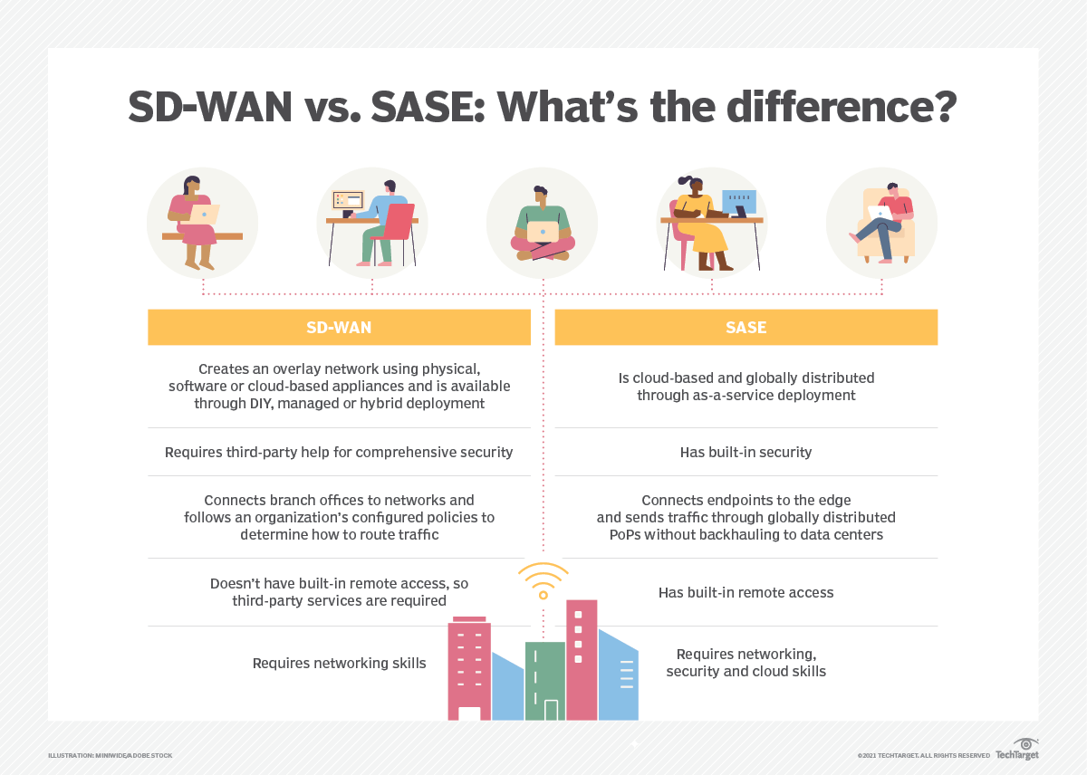
SD-WAN vs. SASE You already know what SD-WAN is. So what is SASE? Secure access service edge (SASE) is a new type of architecture which combines an organization's network and security functionalities into a single cloud service that operates closer to endpoints and distributes traffic quicker than traditional network services. SASE aims to simplify network and security management because it unites an organization's necessary network and security services, such as firewall as a service, secure web gateways and more, into one platform.
While SD-WAN's primary aim is to connect an organization's branch offices to a data center in an intelligent, cloud-friendly way, SASE focuses on endpoints and end-user services. SASE's traffic inspection occurs at various global points of presence (PoPs) rather than backhauling traffic to the data center, as SD-WAN sometimes does.
Deployment of SD-WAN involves creating an overlay network using physical, software or cloud-based appliances and is available through DIY, managed, or hybrid deployment. SADE is a cloud-based, globally distributed through as-a-service deployment.
Further details of SASE will be covered in another document.
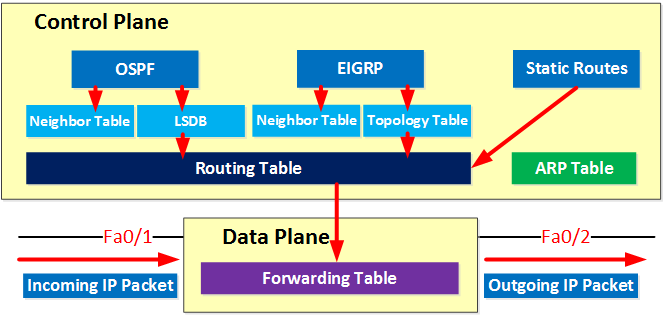
The Control Plane and the Data Plane In networking, a plane is an abstract conception of where certain processes take place. The two most commonly referenced planes in networking are the control plane and the data plane (also known as the forwarding plane).
The control plane is the part of a network that controls how data packets are forwarded. The process of creating a routing table, for example, is considered part of the control plane. ARP tables, neighbor tables, link-state databases (LSDB), and the topology table are also in the control plane.
The data (forwarding) plane actually forwards the packets, while the control plane determines how they should be forwarded. The forwarding table is in the data plane.
Think of the control plane as stoplights that operate at intersections of a city. Meanwhile, the data (forwarding) plane is more like the cars thar drive on the roads, stop at the intersections, and obey the stoplights.
Protocols which create the routing tables in the control plane are ones which you heard of, or will hear of in the future; including, BGP, OSPF, EIGRP, IS-IS.
The network topology refers to the way data flows in a network. The control plane establishes and changes network topology. The network topology is like the way the roads are arranged, and the computing devices within the network are like the destinations that those roads lead to.
SD-WAN's decentralized control plane So... what was the point of talking about control and data planes? The reason is because of how SD-WAN "detatches" the control plane from a physical device and moves it to the cloud. Using the stoplight analogy, normally you'd have to configure a device to make any changes to routing, or the way which the stoplights work. You would additionally need to make changes manually to multiple devices if there are multiples of them. With SD-WAN, changes are defined in the SD-WAN software, which resides in the cloud. You make changes to the stoplight there, and it applies the change. You may also roll out changes to multiple stoplights in bulk, making management and configuration changes far more manageable.
To bring things back to a networking-level, routers all have control planes and data planes. Managing traditional routers involves interacting with each router's control plane to make changes. SD-WAN seeks to fix this issue, along with other WAN-related issues, by moving the control plane to a centralized platform where changes can be made to multiple router's control planes as defined in software. And with the additional benefits of its best-effort WAN routing and intelligent traffic steering, better cloud application and service support, and data encryption, SD-WAN proves itself to be a capable WAN management solution. But understanding the concept of planes and how SD-WAN differs from the traditional model of a on-premises per-device control and data plane router is essential to understanding its benefits in network management and security.
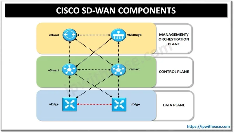
Cisco DNA Center and SD-Access Cisco has its own SD-WAN architecture, shown as follows:
This architecture contains a few layers, including a data plane layer where edge devices, dubbed vEdge devices, reside and connect securely to the decoupled control plane. vSmart devices reside on this plane, and facilitate all routing and mesh functionality, and other functions on the control plane. The management and orchestration plane has all to do with the management of the entire SD-WAN and the spin-up, or orchestration of the SD-WAN. The vBond is responsible for deploying the SD-WAN itself while the vManage is the management component.
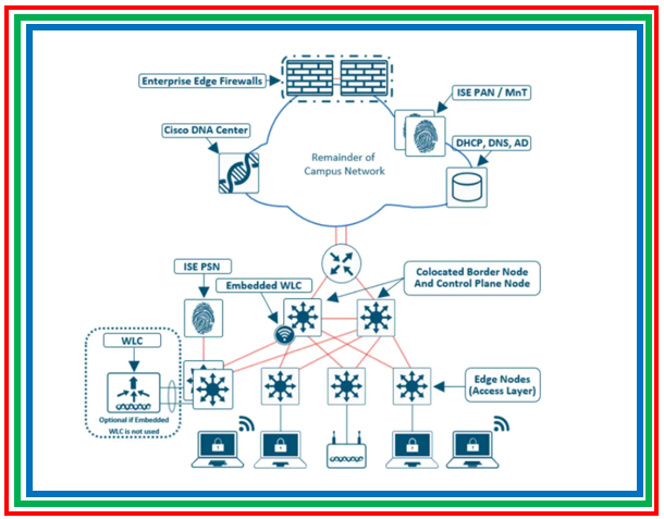
Cisco DNA Center is a network management platform for managing campus networks including wired and wireless infrastructure, and has integration with the vManage for seamless connectivity between SD-WAN and campus networks.
The term SD-Access simply refers to the network architecture design that Cisco DNA Center uses. vManage (now known as Cisco Catalyst SD-WAN Manager) is the management platform that allows you to manage an SD-WAN network.
The SD-Access architecture also applies this principle of decoupling the data plane and control planes, but for campus networks instead of WAN networks. The specifics of SD-Access, and Cisco DNA Center's leverage of this system is beyond the scope of this document. But this shows a real-world example of the principles of SD-WAN being applied to campus networks. By decoupling the data planes and control planes, you facilitate easier network management and deployment by allowing for a central point of control for the control plane itself. |
How to factory reset a Cisco Meraki switch
| Author |
Date |
Revision |
| Samuel Knoppe | 4/9/2024 | 1.0 |
| Related product (if any): |
Cisco Meraki MS120, MS130, MS125, MS210, MS225, MS250, MS350, MS355, MS390, MS410, MS425, MS450 |
| Description: | Shows the steps on how to factory reset a Cisco Meraki MS-series network switch. |
| Symptoms: |
N/A |
| Cause: |
N/A |
| Files Needed: |
N/A |
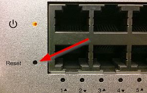
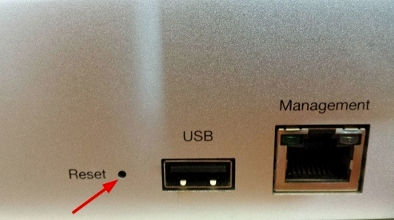
| Steps to Correct: |
|
The OSI model and the basics of network troubleshooting
| Author |
Date |
Revision |
| Samuel Knoppe | 4/10/2024 | 1.1 |
| Related product (if any): |
|
| Description: | Describes the open systems interconnection (OSI) model and how it is used for troubleshooting network-related issues in IT. |
| Symptoms: |
|
| Cause: |
|
| Files Needed: |
|
| Steps to Correct: |
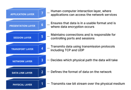
The open systems interconnection (OSI) model is a conceptual model created by the International Organization for Standardization which provides a standard for different computer systems to be able to communicate with each other via standard protocols.
The OSI Model can be seen as a universal language for computer network. It is based on the concept of splitting up a communication system into seven abstract layers, each one stacked upon the last.
*The explanation of the layers and the OSI Model is copied from this CloudFlare article, or otherwise slightly abbreviated. This is not my work: https://www.cloudflare.com/learning/ddos/glossary/open-systems-interconnection-model-osi/
Each layer of the OSI Model handles a specific job and communicates with the layers above and below itself. DDoS attacks target specific layers of a network communication; application layer attacks target layer 7 and protocol layer attacks target layers 3 and 4.
Understanding the OSI Model is vital for understanding how computer networking works, but it's also vital for troubleshooting networking-related issues. So let's start by breaking down what each layer does, starting from the top.
Layer 7: The application layer
This is the only layer that directly interacts with data from the user. Software applications like web browsers and email rely on the application layer to initiate communications. It's important to note that client software applications are not part of the application layer in their entirety; rather, the application layer is responsible for the protocols and data manipulation that the software relies on to present meaningful data to the user.
Some application layer protocols include HTTP/HTTPS and SMTP.
Layer 6: The presentation layer
This layer is primarily responsible for preparing data so that it can be used by the application layer; in other words, layer 6 makes the data presentable for applications to consume. The presentation layer is responsible for translation, encryption, and compression of data.
Two communicating devices may be using different encoding methods, so layer 6 is responsible for translation incoming data into a syntax that the application layer of the receiving device can understand.
If the devices are communicating over an encrypted connection, layer 6 is responsible for adding encryption on the sender's end and decoding the encryption on the receiver's end so that it can present the application layer with unencrypted, readable data.
Finally, layer 6 is also responsible for compressing data it receives from the application layer before delivering it to layer 5. This helps with speed and efficiency of communication by minimizing the amount of data to be transferred.
Layer 5: The session layer
This layer is responsible for opening and closing communication between the two devices. The time between when the communication is open and closed is known as the session. The session layer ensures that the session stays open long enough to transfer all the data being exchanged, and then promptly closes the session in order to avoid wasting resources.
The session layer also synchronizes data transfer with checkpoints. So, if a 100 megabyte file is being transferred, the session layer could set a checkpoint every 5 megabytes. In the case of a disconnect or crash after 52 megabytes have been transferred, the session could be resumed from the last checkpoint, meaning only 50 more megabytes of data need to be transferred. Without the checkpoints, the entire transfer needs to begin from scratch.
Layer 4: The transport layer
Layer 4 is responsible for end-to-end communication between the two devices. This includes taking data from the session layer and breaking it up into chunks called segments before sending it to layer 3. The transport layer on the receiving device is responsible for reassembling the segments into data the session layer can consume.
The transport layer is also responsible for flow control and error control. Flow control determines optimal speed of transmission to ensure that a sender with a faster connection doesn't overwhelm a user with a slow connection. The transport layer also performs error control on the receiving end by ensuring that the data received is complete, and requesting a retransmission if it isn't.
Transport layer protocols include the Transmission Control Protocol (TCP) and the User Data Protocol (UDP).
Layer 3: The network layer
The network layer is responsible for facilitating data transfer between two different networks--so it's quite important. If the two devices are on the same network, then the network layer is unnecessary. Layer 2 will handle it from there. The network layer breaks up segments from the transport layer into smaller units, called packets, on the sender's device, and reassembling these packets on the receiving device. The network layer also finds the best physical path for the data to reach its destination, called routing.
Network layer protocols include IP, the Internet Control Message Protocol (ICMP), the Internet Group Message Protocol (IGMP), and the IPsec suite.
Layer 2: The data link layer
The data link layer is very similar to the network layer, except the data link layer facilitates data transfer between devices on the same network. The data link layer takes packets from the network layer and breaks them into smaller pieces called frames. Like the network layer, the data link layer is also responsible for flow control and error control in intra-network communication (The transport layer only does flow control and error control for inter-network communications--which is a good way to understand that layer's purpose).
Layer 1: The physical layer
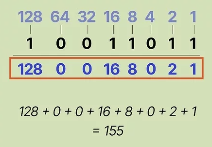
This layer includes the physical equipment involved in the data transfer, such as cables and switches. This is also the layer where the data gets converted into a bit stream, which is a string of 1s and 0s. The physical layer of both devices must also agree on a signal convention so that the 1s can be distinguished from the 0s on both devices.
PS: It's actually possible to convert from binary to decimal. Each position in a binary value corresponds to a specific decimal value. A 1 means that bit is "activated" and can be added to the sum. The sum will equal one octect, if you're talking about an IPv4 address.
How data flows through the OSI Model
In order for human-readable information to be transferred over a network from one device to another, the data must travel down the seven layers of the OSI Model on the sending device and then travel up the seven layers on the receiving end.
For example, if a user wants to send an email, the user composes his email in an email application on his laptop and clicks "send". His email application will pass his email message over to the application layer, which will pick a protocol (SMTP) and pass along the data to the presentation layer. The presentation layer will then compress the data, and then it will hit the session layer, which will initialize the communication session.
The data then hit's the sender's transportation layer where it will be segmented, then those segments will be broken up into packets at the network layer, which will be broken down even further into frames at the data link layer. The data link layer will then deliver those frames to the physical layer, which will convert the data into a bitstream of 1s and 0s and send it through a physical medium, such as a cable.
Once the the recipient's computer receives the bit stream through a physical medium (such as their WiFi), the data will flow through the same series of layers on their device, but in the opposite order. First the physical layer will convert the bitstream from 1s and 0s that get passed down to the data link layer. The data link layer will then reassemble the frames into packets for the network layer. The network layer will then make segments out of the packets for the transport layer, which will reassemble the segments into one piece of data.
The data will then flow into the receiver's session layer, which will pass the data along to the presentation layer and then end the communication session. The presentation layer will then remove the compression and pass the raw data up to the application layer. The application layer will then feed the human-readable data along to the recipient's email software, which will allow them to read the sender's email on their laptop screen.
How the OSI Model is used in network troubleshooting
Because the OSI Model gives you a good idea on how traffic flows through networks, and gives you protocols which are tied exclusively to the functionality of those layers, it provides a good, hierarchical approach to troubleshooting network problems.
When you encounter issues with the network, the ethos is to start from the ground-up. Or, try the easiest, most obvious thing first and work your way up from there. So when there's a network problem, check layer 1 first. Are cables plugged in? Is the WiFi turned on? A lot of network problems reside on layer 1, so it's good to check as a part of your troubleshooting process.
If cables are good, check layer 2. As mentioned before, layer 2 is responsible for flow and error control in intra-network communications. If there is a problem during transmission, you will likely get a lot of retransmissions, showing up as cyclic redundancy check (CRC) errors on a switch's management dashboard or interface configuration page.
If there's a lot of retransmissions, it usually indicates some kind of issue with the physical layer. This could be interference in a wireless, or some kind of problem with Ethernet infrastructure. If there are a multitude of people having issues, it's not impossible for it to be something like this. Maybe an uplink cable is bad, or maybe wireless AP placement is poor, etc.
If layer 1 and 2 are fine, check layer 3. Can you ping the machine's loopback? If not, it may be a bad NIC or some other problem with the device such as a bad driver. Being unable to ping the devices own IP address may also mean a problem with a NIC, but it could mean a firewall issue, if you can ping the loopback but not the IP address. One thing to check in that scenario is if the person has a VPN turned on.
Layer 4 issues are somewhat rare. It's possible a TCP handshake may fail, but typically these are retransmitted. UDP kind of just "yeets" data out there regardless of what form it takes. However, if you find that specifically UDP traffic is being blocked either via a Wireshark session or something, it may be because of an Access Control List (ACL) on a router, L3 switch, or a security gateway or firewall. You have the ability to block protocols from layer 4 via an ACL. So check your ACL rules if you see a pattern of TCP or UDP traffic being blocked.
Layers 5, 6 and 7 are considered the "data stream" of an application. Most often these are treated as one. Troubleshooting usually involves troubleshooting issues with the layer 7 application. (i.e. Outlook is having issues), but rarely you may see layer 5 and 6 problems. You may have a firewall rule which restricts a layer 5 protocol, like SCP, RPC, NetBIOS, etc.
Problems with layer 6 involve data integrity and potentially corruption. Check the data format and encoding of the L7 application, as well as the conversation, compression, encryption, and integrity and validation of the data using something like Wireshark. Data should not be in plaintext. If it is, then something is wrong with layer 6.
It's still important to note that generally speaking, most problems occur at the bottom 4 layers, and sometimes at layer 7, but rarely layers 5 and 6. |

How a network switch works
| Author |
Date |
Revision |
| Samuel Knoppe | 4/11/2024 | 1.0 |
| Related product (if any): |
N/A |
| Description: | Explains the fundamentals of network switches, what they are used for, and how they work. |
| Symptoms: |
N/A |
| Cause: |
N/A |
| Files Needed: |
N/A |
| Steps to Correct: |
What is a network switch? A network switch is a device which connects network devices and allows users to perform intra-network data exchange data packets via frames. Switches can be both hardware and software, and operate at Layer 2, the data link layer, in the OSI Model.
The way a switch operates is that it distributes information to the one device a frame is destined for, including some other switch, a router, or a user's computer, rather than several other devices in the network at once.
The majority of switches use Ethernet as its main Layer 1 medium of choice, but some also use fiber optics, InfiniBand, and more.
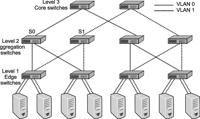
How does a network switch work? Network switches can work in one of three ways in a network:
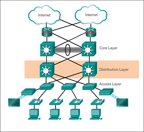
This diagram provides an overview of what these three types of network switches will look like in a network architecture. This follows a design philosophy in network engineering calling the 3 Layer Hierarchical Network Model.
The 3-tier model shown provides a mixture of high redundancy for all three layers. Redundancy is the main key appeal of this model. Note that this model doesn't include just network switches, but routers as well. But the image showing the layers of switches follows this design philosophy of redundancy as well.
Why have this? In massive enterprise network environments, downtime is a no-go. You also need to have speed and reliability for your network. Where access switches provide network coverage, a distribution layer is optionally used to facilitate faster and redundant connections between other access switches. While the core provides a high-speed backbone for the network and connects to the Internet and other remote sites, and more.
Smaller businesses may not have or need a distribution layer, and may only have an access and core layer, or, for very small businesses, basically only have an access layer.
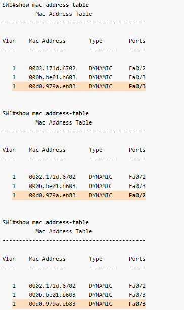
What happens when data comes into the switch? Okay, so I lied about the last section. This is the section where I actually explain how a switch works. Whenever a device is connected to a switch, the switch notes the device's MAC address, which is baked into the network device's NIC. The NIC attaches to a Layer 1 media like an ethernet cable, which connects it to a switch. The switch uses the MAC address of the device to identify which device's outbound packets are being send, and where to send inbound ones.
The MAC address identifies the physical device and does not change in a way an IP address might change.
When a packet enters the switch--packets actually mean frames, when we're talking about network switches--the switch reads the header, then matches the destination MAC address or addresses and sends the frame out of the appropriate ports that lead to destination devices.
But what if a network switch doesn't know where a destination MAC address is? What then? In that situation, it will send out a broadcast frame out of every one of its ports, except for the port it received the frame on that included the unknown destination MAC address. If the destination is near, the switch will record the port where the destination MAC is attached to into something called a forwarding information base (FIB) or MAC table, which includes a cache of all MAC address to port mappings. After it has been recorded, the switch will be able to simply forward traffic out of that port if it needs to reach that MAC address.
The danger of broadcast storms I want you to envision a scenario. You have a network with two access switches, and one core switch. All three are interconnected, so there is redundancy in play. One access switch receives a frame with an unknown MAC, so it floods that frame on all its ports except the one the frame came in on. The second access switch and the core switch also receive the broadcast frame, and perform the same procedure. The first access switch receives the broadcast again, and so does the second, and the core... dramatically increasing network activity until the switches shut off.
So... what happened? Why did the switches shut off? The reason is because of a broadcast storm (also called BUM frames). This is where broadcast frames are looped indefinitely between a redundant array of network switches, creating an excess of network activity, increasing CPU usage until the switches shut-off due to built-in protection parameters.
Another problem arises when a broadcast storm occurs, called MAC table instability. A MAC address can only be tied to one port, but during a storm, multiple copies of the same frame are coming in on multiple ports, creating inconsistency and even more BUM traffic to the other switches, exacerbating the problem even further.
There also a third problem created when a broadcast storm happens. End devices will receive multiple copies of the same frame. This can result in high CPU usage and may even crash end-user devices!
Spanning-tree protocol--a network's sword and shield against deadly loops So... now you understand fully just how catastrophic broadcast storms are. How the hell do you prevent them? Luckily most network switches have a protocol which is used to defend against loops in networks with redundant paths called Spanning Tree Protocol (STP). This protocol's entire job is to prevent these loops by strategically blocking certain ports on the network as to close off loops, but still allowing said port to be used as a redundant link if its counterpart goes down. So you get the benefits of redundancy without the fear of deadly loops.
STP: No, you furry little fucker. These loops are mine! You cannot have them!
The specifics of how STP works and the election process it goes through is beyond the scope of this document, but just know it's the thing that's keeping your nice redundant layer 2 switch topology from completely nuking your entire network and creating a really bad day in the office.
Switches versus hubs In the olden days, hubs were the shit and switches weren't a thing at all. Hubs function simply like this; I receive traffic, I shit traffic out of all ports. I'm sure you can see the issue here. Hubs are very stupid and simply just spit out traffic. Back then, it worked fine since bandwidth needs were lower, but that ain't going to fly today at all. Doesn't help that most at the time capped out at, like, 10MB at the ports.
Another frequent problem of hubs, is that they ran at half duplex; meaning, they can only send or receive data. But not at the same time. If data is sent and received at the same time, data collisions occur, resulting in data loss and errors.
Network switches fix all these issues by first only sending traffic to ports of a specific device (once it has learned its MAC and port binding), and also by being able to run at full duplex on its port. Meaning it can send data back and forth at the same time, giving full access to the bandwidth of the connection to the switch.
Did you know? If a network switch's MAC table gets full, it will fail over to broadcast mode and start to broadcast the traffic to all ports in that VLAN, effectively turning it into a hub!
|

How a router works
| Author |
Date |
Revision |
| Samuel Knoppe | 4/12/2024 | 1.0 |
| Related product (if any): |
N/A |
| Description: | Describes what a network router is, how it works, and some basic concepts relating to its functions. |
| Symptoms: |
N/A |
| Cause: |
N/A |
| Files Needed: |
N/A |
| Steps to Correct: |
What is a router? A router is a Layer 3 network device which routes IP packets. Without it, network devices will not be able to talk to each other. It facilitates communication by creating a local area network (LAN) which devices join, and it uses a routing table to route traffic to the Internet, and other remote networks.
Routers differ from modems in that modems connect your home and business to Internet access via your ISP, whilst your router is the device which you actually connect to on your network--which your modem also connects to.
How does a router work? A router figures out the fastest path between devices connected on a network, and sends data to those paths. To do this, routers use what's called a metric value or preference number. So if a router has to choose between two routes to the same location, it will choose the one with the lowest metric. Metrics are stored and shown in the routing table. P.S., there are different ways in which a router learns routes. Routes can be learned either statically or dynamically and generally speaking, static routes tend to have a higher preference when compared to a dynamic route. How a router chooses a route to a network via static route versus a route learned via a dynamic routing protocol, is via its administrative distance (AD). So the flow is Choose lowest AD route type/protocol > Choose route with lowest metric.
The routing table is a list of all possible paths in your network. When a router receives IP packets that need to be routed to another network, the router looks at the packet's IP address and then searches the routing table for routing information. Learning about routing tables is crucial for managing networks regardless of what protocols are being used.
Managing routers involves making changes when necessary. This involves logging into your router via software, webpage, or through a terminal session. For example, you may need to change login passwords, encrypt the network, create port forwarding rules, or update the router's firmware.
NOTE: Traffic destined for another host on the same network will almost never go to the router. The network switch will used its forwarding information base (FIB) to send Layer 2 frames to the host instead.
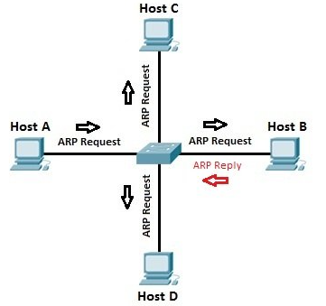
ARP and the routing table Address Resolution Protocol (ARP) is a Layer 2 protocol that routers use to create a table that binds IP addresses to MAC addresses. Or in other words, it binds an IP address to the hardware device on the network. This is important since routers are normally Layer 3 devices on the OSI model. A router needs to know how an IP address relates to a Layer 2 MAC address, and ARP is how it figures this out.
If a host wants to send a packet to another host via it's IP address, the router will send an ARP request broadcast from which it will receive a reply with the MAC address the host needs for Layer 2 communication to be possible. From there, the router uses its own forwarding information base (FIB) to send Layer 2 frames down to downstream switches, or straight to the host machine (if directly connected to the router).
Static routes and routing protocols In order for a router to send traffic, it must use its routing table. If the router has network interfaces configured either by DHCP or manually, it implicitly knows the routes to that network and populates the routing table.
You can also configure a static route, which is where you manually define the route to a network.
There are also dynamic routes learned via routing protocols. Routing protocols dynamically discover and populate the routing table without you having to manually add routes. This can create better flexibility and scalability for larger networks. Some examples of dynamic routing protocols include:
The specifics of how each routing protocol works differs per protocol and is beyond the scope of this document, but each one has its own configuration and discovery process.
Distinguishing between metrics and administrative distance (AD) I want to distinguish this again since we know more about routing protocols.
The hierarchy of choice is to choose the route with the lowest AD. If there are multiples of routes with the same AD, it will choose the route with the lowest metric value, assuming there are multiple routes going to the same network.
Metric values are calculated based on numerous factors like the amount of hops, to more complex factors like bandwidth usage depending on the routing protocol. Another thing is that dynamic routing protocols will use their algorithms to determine the fastest possible route in order to come up with the lowest metric value route to a specific network. |
How OSPF works
| Author |
Date |
Revision |
| Samuel Knoppe | 4/15/2024 | 1.1 |
| Related product (if any): |
Routers |
| Description: | Describes what OSPF is and how it works. |
| Symptoms: |
N/A |
| Cause: |
N/A |
| Files Needed: |
N/A |
| Steps to Correct: |
What is OSPF? Open Shortest Path First (OSPF) is an Interior Gateway Protocol used to distribute routing information within an Autonomous System (AS). Or, in layman terms, it is a dynamic routing protocol used to distribute routes within internal networks.
So... what the hell are those other things? Well, for starters, an Autonomous System refers to a collection of independent networks that are controlled by a single entity, such as an ISP. Interior Gateway Protocols (IGPs) are used to route traffic within each network of an AS, such as a company's LAN.
There are three types of IGPs, including
A distance-vector (DVR) routing protocol calculates the best route based on distance. Distance is usually measured in hops, though the metric could be measured in delay, packets lost, or something similar. If the distance metric is a hop, then each time a packet passes through a router, a hop is considered to have traversed. The route with the least number of hops to a given network is concluded to be the best route to that network. Some examples of distance-vector routing protocols include:
A link-state routing protocol, also called shortest-path-first protocols, have a complete picture of the network topology. Hence, they have a greater idea about the whole network than any distance vector protocol. Three separate tables are created on each link state routing enabled routing. One table is used to hold details about directly connected neighbors, another is used to hold the topology of the entire internetwork, and the last one is used to hold the actual routing table. Link state protocols send information about directly connected links to all the routers in the network. Some include:
There also exists hybrid routing protocols in the sense that they used aspects of both distance vctor and link state protocols.
So... what exactly is OSPF, then? And what's with all this preamble? Well, it's important to understand the distinction between IGPs and EGP (exterior gateway protocols--routes things over the Internet, basically), the concept of autonomous systems, and the difference between distance-vector and link-state protocols, because OSPF was made due to the need for a high functionality non-proprietary IGP for the TCP/IP protocol family. Now that you know these things, I can move forward.
OSPF was made to used link-state technology due to the limitations of distance-vector-based routing. The most common distance-vector protocol used back in the day was RIP (routing information protocol). Its limits included:
Enhancements were made to RIP via RIPv2, which addressed issues with lack of VLSM support, authentication, and multicast routing updates, but it wasn't enough. OSPF, on the other hand, fixes most of the issues presented:
In essence, OSPF is more efficient, complex, and secure due to it using a link-state algorithm to calculate its routes instantly. It's the most commonly used dynamic routing protocol for internal networks, and is still used today in many network topologies. But due to its changes and improvements, configuration is more complex alongside troubleshooting, and there is more CPU overhead.
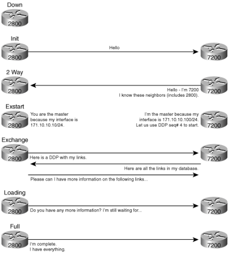
How does OSPF work? As stated previously, OSPF uses a link-state algorithm known as the Shortest Path First Algorithm. It is used to build and calculate the shortest path to all destinations. The shortest path is calculated with the Dijkstra algorithm.
The algorithm itself is complicated. This is a high level look at the various steps in the algorithm:
The algorithm places each router at the root of a tree and calculates the shortest path to each destination based on the cumulative cost required to reach that destination.
Each router has its own view of the topology even though all the routers build a shortest path tree which uses the same link-state database. These sections indicate what is involved in the creation of a shortest path tree.
|
How IS-IS works
| Author |
Date |
Revision |
| Samuel Knoppe | 4/18/2024 | 1.0 |
| Related product (if any): |
|
| Description: | Describes how the Intermediate-Systems to Intermediate-Systems (IS-IS) routing protocol works and what it is. |
| Symptoms: |
N/A |
| Cause: |
N/A |
| Files Needed: |
N/A |
| Steps to Correct: |
What is IS-IS? The IS-IS (Intermediate-Systems to Intermediate-Systems) protocol is an interior gateway protocol (IGP) that uses link-state information to make routing decisions. Just like OSPF, another IGP, it uses the shortest-path-first (SPF) algorithm to determine routes.
IS-IS evaluates the topology changes and determines whether to perform full SPF recalculation or a partial route calculation (PRC). This protocol was orginally developed for routing International Organization for Standardization (ISO) Connectionless Network Protocol (CLNP) packets.
Just like OSPF routing, IS-IS uses hello packets that allow network convergence to occur quickly when changes are detected. IS-IS uses SPF to determine routes. Using SPF, IS-IS evaluated network topology changes and determines if a full or partial route calculation is required. The main difference between OSPF and IS-IS is that where OSPF requires IP configuration, IS-IS uses CLNP packets, which are connectionless, to send information.
How does IS-IS work? An IS-IS network is a single autonomous system (AS), also called a routing domain, that consists of end systems and intermediate systems. End systems are network entities that send and receive packets. Intermediate systems send and receive packets and relay (forward) packets. (Intermediate system is the Open System Interconnection [OSI] term for a router.) ISO packets are called network PDUs.
Why are we discussing this terminology? Well, IS-IS doesn't use IP addresses like OSPF does, as mentioned above. The ISO developed CLNP packets and an entire suite of other functionality separate to that of IP to make a "connectionless" IGP.
In IS-IS, a single AS can be divided into smaller groups called areas. Routing between areas is organized hierarchically, allowing a domain to be administratively divided into smaller areas. This organization is accomplished by configuring Level 1 and Level 2 intermediate systems. Level 1 systems route within an area; when the destination is outside an area, they route toward a Level 2 system. Level 2 intermediate systems route between areas and toward other ASs. No IS-IS area functions strictly as a backbone.
Level 1 routers share intra-area routing information, and Level 2 routers share interarea information about IP addresses available within each area. Uniquely, IS-IS routers can act as both Level 1 and Level 2 routers, sharing intra-area routes with other Level 1 routers and interarea routes with other Level 2 routers.
The propagation of link-state updates is determined by the level boundaries. All routers within a level maintain a complete link-state database of all other routers in the same level. Each router then uses the Dijkstra algorithm to determine the shortest path from the local router to other routers in the link-state database.
ISO Network Addresses IS-IS uses ISO network addresses. Each address indentifies a point of connection to the network, such as a router interface, and is called a network service access point (NSAP).
IS-IS supports multiple NSAP addresses on the loopback lo0 interface.
An end system can have multiple NSAP addresses, in which case the addresses differ only in the last byte (called the n-selector). Each NSAP represents a service that is available in that node. In addition to having multiple services, a single node can belong to multiple areas.
Each network entity also has a special network address called a network entity title (NET). Structurally, an NET is identical to an NSAP address but has an n-selector of 00. Most end systems and intermediate systems have one NET. Intermediate systems that participate in multiple areas have multiple NETs.
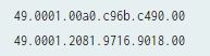
Here is an example of a couple of ISO addresses following the IS-IS format:
NETs take several forms, depending on your network requirements. NET addresses are hexadecimal and range from 8 octets to 20 octets in length. Generally, the format consists of an authority and format identifier (AFI), a domain ID, an area ID, a system identifier, and a selector. The simplest formbat omits the domain ID and is 10 octets long. For example, the NET address 49.0001.1921.6800.1001.00 consists of the following parts:
The system identifier must be unique within the network. For an IP-only network, it is recommended using the IP address of an interface on the router. Configuring a loopback NET address with the IP address is helpful when troubleshooting is required on the network.
The first portion of the address is the area number, which is a variable number from 1 through 13 bytes. The first byte of the area number (49) is the authority and format indicator (AFI). The next bytes are the assigned domain (area) identifier, which can be from 0 through 12 bytes. In the above example, the area is 0001.
The next six bytes form the system identifier. The system identifier can be any six bytes that are unique throughout the entire domain. The system identifier commonly is the media access control (MAC) address (for the first example, 00a0.c96b.c490) or the IP address expressed in binary-coded decimal (BCD) (as in the second example, 2081.9716.9018, which corresponds to an IP address 208.197.169.18). The last byte (00) is the n-selector.
IS-IS packets Each IS-IS PDU shares a common header. IS-IS uses the following PDUs to exchange protocol information:
IS-IS vs. OSPF Both IS-IS and OSPF are IGPs. Meaning, they can be used for intra-area routing. However, IS-IS has key differences, including:
In general, OSPF is a intradomain routing protocol and is based on link-state routing technology. It has introduced new concepts that are authentication of routing updates, VLSM, root summarizations, etc.
IS-IS is a standardized link-state protocol that was developed to the definitive routing protocol for the OSI Model. IS-IS is a Link-state IGP. Link-state protocols are distinguished by the circulation of the information required to build a complete network connectivity map on each participating router. This map is used to calculate the shortest path to destinations.
Predominately, IS-IS is used in an ISP environment.
|
How BGP works
| Author |
Date |
Revision |
| Samuel Knoppe |
04/19/2024 | 1.3 |
| Related product (if any): |
N/A |
| Description: | Describes what Border Gateway Protocol (BGP) is and what it does, and goes into detail about Exterior Gateway Protocols (EGPs) and how they relate to Interior Gateway Protocols (IGPs). |
| Notes: |
95% copywrited from this CloudFlare article. |
| Files Needed: |
N/A |
| Information: |
What is BGP? Border Gateway Protocol (BGP) is an Exterior Gateway Protocol (EGP) that makes the Internet work by enabling data routing between autonomous systems (AS). BGP can be seen as the postal service for the Internet. When someone submits data via the Internet, BGP is responsible for looking at all of the available paths that data could travel and picking the best route.
BGP is generally considered a path-vector routing protocol, which sends peers information on which path traffic on a network will go. This includes which ASes that traffic will travel through. Distance-vector protocols like the IGP RIPv2 only counts hops, and is unable to know which exact path traffic will take.
BGP relies on path-vector route discovery due to the visibility it provides. This is also the reason why it's not a link-state routing protocol, since link-states do not have complete visibility and may introduce unwanted traffic via its LSU (link state update) packets, and so on. The IGP OSPF uses link-state routing.
Because BGP uses path-vector discovery, convergence times for BGP is the slowest among the routing protocols used today.
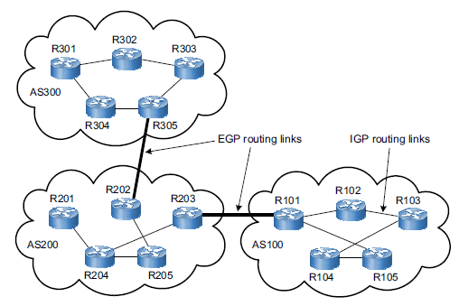
The Internet is a network of networks. It is broken up into hundreds of thousands of smaller networks known as autonomous systems (AS). Each of these networks is essentially a large pool of routers run by a single organization. If we see BGP as the postal service of the Internet, ASes are like individual post office branches. A town may have hundreds of mailboxes. They forward outbound transmissions to the AS, which then uses BGP routing to get these transmissions to their destinations.
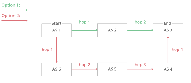
The above example illustrates a simplified version of BGP where there are only six ASes on the Internet. If AS1 needs to reach AS3, it has two different options:
This simplified version makes the decision seem straightforward. The first option has fewer hops then the second and thus is the quickest, most efficient route. Now, imagine that there are hundreds of thousands of ASes and that hop count is only one part of a complex selection algorithm. That is the reality of BGP routing on the Internet.
The Internet is constantly changing, with new systems popping up left and right, or existing systems becoming unavailable. Because of this, every AS must be kept up to date with information regarding new routes as well as obsolete routes. This is done through peering sessions where each AS connects to neighboring ASes with a TCP/IP connection for the purpose of sharing routing information. Using this information, each AS is equipped to properly route outbound data transmissions coming from within.
This is where the Post Office analogy falls apart. Unlike post office branches, autonomous systems are not all part of the same organization. In fact, they often belong to competing businesses. Because of this, BGP routes sometimes take business considerations into account. ASes often charge each other to carry traffic across their networks, and the price of access can be factored into which route is ultimately selected.
Who owns and operates autonomous systems? Typically ASes belong to ISPs or other large organizations such as tech companies, universities, government agencies, and scientific institutions. Each AS wishing to exchange routing information must have a registered autonomous system number (ASN). Internet Assigned Numbers Authority (IANA) assigns Regional Internet Registries (RIRs), which then assigns them to ISPs and networks. ASNs are 16 bit numbers between one and 65534 and 32 bit numbers between 131072 and 4294967294. As of 2018, there are approximately 64,00 ASNs in use worldwide. These ASNs are only required for external BGP.
The differences between external BGP and internal BGP: IGP vs. EGP Routes are exchanged over the Internet using external BGP (eBGP). Autonomous systems have the option to use an internal version of BGP to route through their internal networks, which is known as internal BGP (iBGP). It should be noted that internal BGP is NOT a requirement for using external BGP. Autonomous systems can choose from a number of internal protocols to connect the routers on their internal network.
iBGP is an example of an interior gateway protocol (IGP). ASes have the option to use iBGP, but also IS-IS and OSPF, EIGRP, etc. eBGP is the main external gateway protocol (EGP) that is used. eBGP is like international shipping. There are certain standards and guidelines that need to be followed when shipping a piece of mail internationally. Once it reaches its destination country, it has to go through the destination country's local mail service to reach its final destination. Each country has its own internal mail service that does not necessarily follow the same guidelines as those of other countries. Similarly, each autonomous system can have its own internal routing protocol for routing data within its own network. Or, one AS may use primarily IS-IS for internal routing while another uses OSPF.
What are BGP attributes? Attributes are additional factors BGP uses alongside hop counts when deciding the most efficient path for network traffic. This is useful when BGP needs to decide between multiple options, like administrative distances and metrics do for routers in a routing table. Many routers allow administrators to customize attributes for more granular control over how traffic flows on their networks. Some examples of BGP attributes are:
There are several other BGP attributes as well. All these attributes are ordered by priority for BGP routers--for example, a BGP router first checks to see which route has the highest weight, then checks local preference, then checks to see if the router originated the route, and so on. So if all routes received have an equal weight, the router selects a path based on preference instead. This acts similarly to routing tables where if you have multiple routes to the same network with the same administrative distance, it picks the one with the lowest metric value.
BGP's flaws BGP has flaws relating to the route-sharing function of BGP relying on trust, and autonomous systems implicitly trusting the routers that are shared with them. When peers announce incorrect route information, intentional or not, traffic goes where it is not supposed to, potentially with malicious results.
One incident involved a Turkish ISP called TTNet accidentally advertised incorrect BGP routes to its neighbors. These routes incorrectly claimed TTNet itself was the best destination for all traffic on the Internet. As these routes spread further to more autonomous systems, a massive disruption occurred, creating a one-day crisis where many people across the world were not able to access some or all of the Internet.
Another incident involved a Pakistani ISP attempting to use a BGP route to block Pakistani users from visiting YouTube. The ISP then accidentally advertised these routes with its neighboring ASes and the route quickly spread across the Internet's BGP network. This route sent users trying to access YouTube to a dead-end, which resulted in YouTube being inaccessible for several hours.
Another incident occurred in June 2019 when a small Pennsylvania company became the preferred path for routes through Verizon's network, causing much of the Internet to become unavailable to users for several hours.
These are examples of a practice called BGP hijacking, which does not always happen accidentally. In April 2018, attackers deliberately created bad BGP routes to redirect traffic that was meant for Amazon's DNS service. These attackers were able to steal over $100,000 worth of cryptocurrency by redirecting traffic to themselves.
BGP hijacking can be used for several kinds of attacks:
How to secure BGP Some progress has been made in securing BGP. Most notably, a security framework for routing called Resource Public Key Infrastructure (RPKI) was introduced in 2008. RPKI uses cryptographically signed records called Route Originate Authorization (ROAs) to validate which network operate is allowed to announce an organization's IP addresses using BGP. This ensures that only authorized parties are announcing an organization's prefixes.
But RPKI alone isn't enough. Over 50% of the top ISPs support RPKI to some extent, but a larger majority is needed to fully secure BGP. Network operators can protect their networks by implementing RPKI and using network alerting technologies, which alerts customers when unauthorized parties are advertising their prefixes. |
MPLS - A WAN routing technique
| Author |
Date |
Revision |
| Samuel Knoppe |
4/22/2024 | 1.0 |
| Related product (if any): |
N/A |
| Description: | Describes Multiprotocol Label Switching (MPLS) and how it works. |
| Notes: |
Need perquisite knowledge of the OSI Model, network switching, network routing, EGPs and IGPs, OSPF, IS-IS, and BGP. |
| Files Needed: |
N/A |
| Information: |
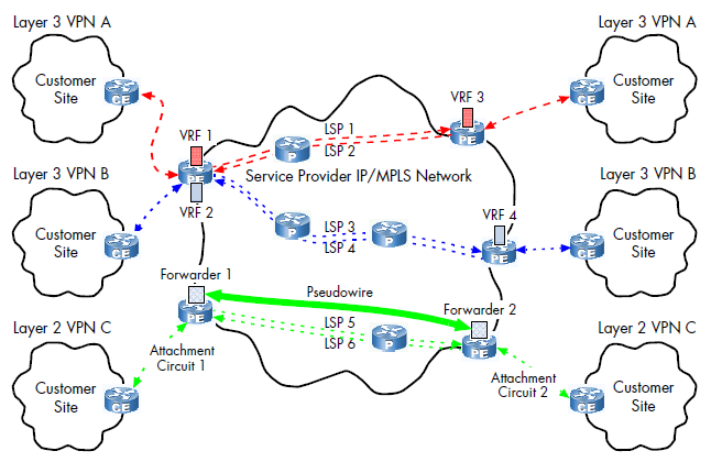
What is MPLS? Multiprotocol label switching (MPLS) is a technique for speeding up network connections developed in the 1990s. Normally the public Internet forwards packets from one router to another, but MPLS sends packets along a predetermined network path. This ideally results in less time spend deciding where to forward each packet, since each packet takes the same path every time.
Another way of looking at this is that MPLS defines different network paths instead of a series of intermediary destinations--routers.
MPLS is considered to operate as OSI layer 2.5, so below the network layer (layer 3) and above the data link layer (layer 2).
How does MPLS work? Normally anything sent from one network to another is divided up into smaller pieces called packets instead of getting sent all at once. For these packets to reach their intended destination each router hop must reference and maintain a routing table until the packet reaches the same network as its destination IP address. This approach works well in most cases, since most of the Internet runs using IP addresses and routing tables, but some organizations want their data to travel fast over paths they can directly control.
The path a packet takes under the routing method can be different each time, but with MPLS packets take the same path each time. The way this is done in a network that uses MPLS is that each packet is assigned a forwarding equivalence class (FEC). The network paths that packets can take are called label-switched paths (LSP). A packet's class (FEC) determines which path (LSP) the packet will be assigned to. Packets with the same FEC will follow the same LSP.
Each packet can contain one or more labels, and all labels are contained in an MPLS header, which is added on top of all of the other headers attached to a packet. FECs are labeled within each packet's labels. Routers do not examine the other headers; meaning, they can essentially ignore the IP header entirely. Instead, they examine the packet's label and direct the right packet to the right LSP. Because MPLS-supporting routers only need to see the MPLS labels attached to a packet, MPLS can work with any protocol, hence the name. It doesn't matter how the rest of the packet is formatted as long as the router can read the MPLS labels at the front of the packet.
So for instance, you can have traffic routed via BGP be encapsulated within an MPLS header, which label switches those packets to a designated MPLS router, then the MPLS header is removed and the BGP headers do their thing and route the traffic over to its destination. This will also work with IS-IS traffic, and OSPF--it doesn't matter what routing protocol is used, if any.
This image displays an example of an MPLS topology with VPNs configured. Notice the various LSPs, and the FECs (VRF 1, 2, 3, 4).
The drawbacks of MPLS The biggest drawback to MPLS is the lack of encryption. MPLS can be 'private' in the sense that an organization uses certain MPLS paths, but without the use of a VPN, this traffic is sent via plaintext.
Another significant drawback is cost. MPLS is more expensive than regular Internet service.
MPLS also has long setup times. Setting up complicated dedicated paths across one or more large networks takes time. LSPs have to be manually configured by the MPLS vendor or by the organization using MPLS. This makes scaling up networks quickly very difficult.
There is also the challenge of cloud services. Since cloud services rely on direct connections to cloud servers, cloud services and applications may not work properly.
When is MPLS used? Speed and reliability are the main reasons why MPLS is used. So real-time traffic like voice and video calls are common traffic that requires extra speed and is more sensitive to latency issues and would benefit the most from MPLS.
MPLS is also used to set up wide area networks (WANs). However, as discussed above, scaling these WANs up is quite difficult. Some ISPs are known to use MPLS for their network traffic. Certain organizations like school districts also are known to use MPLS.
SD-WAN: The future of WAN routing MPLS has been used for nearly two decades, and is costly and time-consuming to create and maintain. Software-defined wide-area networking (SD-WAN) is a software-based approach to managing the WAN. SD-WAN is an evolution in connectivity from traditional MPLS technology, enabling traffic prioritization, and enables customers to take advantage of various transport methods including MPLS circuits, direct Internet broadband, and LTE/5G. It makes management simplier by making it independent of transport layers.
Cloud services and remote work are the biggest benefits SD-WAN has over traditional MPLS. It provides edge users with more secure and reliable connects when they access enterprise applications and data while providing a predictable user experience. SD-WAN allows enterprises to prioritize data based on its type and then choose the shortest, fastest, and most reliable and cost-effective path available.
However, despite its benefits over MPLS, some organizations may not need to SD-WAN or cannot use it due to security and compliance reasons. Some organizations do not use cloud services and thus do not have a need for something like SD-WAN. Some use hybrid services and use both.
The specifics of SD-WAN and how it works are beyond the scope of this document, but given its ability to more easily support cloud services, its likely to rise in prominence in the coming years. However, due to MPLS's reliability and long-time standing, its unlikely to go away anytime soon, either. |