
The OSI model and the basics of network troubleshooting
| Author |
Date |
Revision |
| Samuel Knoppe | 4/10/2024 | 1.1 |
| Related product (if any): |
|
| Description: | Describes the open systems interconnection (OSI) model and how it is used for troubleshooting network-related issues in IT. |
| Symptoms: |
|
| Cause: |
|
| Files Needed: |
|
| Steps to Correct: |
The open systems interconnection (OSI) model is a conceptual model created by the International Organization for Standardization which provides a standard for different computer systems to be able to communicate with each other via standard protocols.
The OSI Model can be seen as a universal language for computer network. It is based on the concept of splitting up a communication system into seven abstract layers, each one stacked upon the last.
*The explanation of the layers and the OSI Model is copied from this CloudFlare article, or otherwise slightly abbreviated. This is not my work: https://www.cloudflare.com/learning/ddos/glossary/open-systems-interconnection-model-osi/
Each layer of the OSI Model handles a specific job and communicates with the layers above and below itself. DDoS attacks target specific layers of a network communication; application layer attacks target layer 7 and protocol layer attacks target layers 3 and 4.
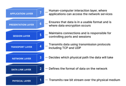
Understanding the OSI Model is vital for understanding how computer networking works, but it's also vital for troubleshooting networking-related issues. So let's start by breaking down what each layer does, starting from the top.
Layer 7: The application layer
This is the only layer that directly interacts with data from the user. Software applications like web browsers and email rely on the application layer to initiate communications. It's important to note that client software applications are not part of the application layer in their entirety; rather, the application layer is responsible for the protocols and data manipulation that the software relies on to present meaningful data to the user.
Some application layer protocols include HTTP/HTTPS and SMTP.
Layer 6: The presentation layer
This layer is primarily responsible for preparing data so that it can be used by the application layer; in other words, layer 6 makes the data presentable for applications to consume. The presentation layer is responsible for translation, encryption, and compression of data.
Two communicating devices may be using different encoding methods, so layer 6 is responsible for translation incoming data into a syntax that the application layer of the receiving device can understand.
If the devices are communicating over an encrypted connection, layer 6 is responsible for adding encryption on the sender's end and decoding the encryption on the receiver's end so that it can present the application layer with unencrypted, readable data.
Finally, layer 6 is also responsible for compressing data it receives from the application layer before delivering it to layer 5. This helps with speed and efficiency of communication by minimizing the amount of data to be transferred.
Layer 5: The session layer
This layer is responsible for opening and closing communication between the two devices. The time between when the communication is open and closed is known as the session. The session layer ensures that the session stays open long enough to transfer all the data being exchanged, and then promptly closes the session in order to avoid wasting resources.
The session layer also synchronizes data transfer with checkpoints. So, if a 100 megabyte file is being transferred, the session layer could set a checkpoint every 5 megabytes. In the case of a disconnect or crash after 52 megabytes have been transferred, the session could be resumed from the last checkpoint, meaning only 50 more megabytes of data need to be transferred. Without the checkpoints, the entire transfer needs to begin from scratch.
Layer 4: The transport layer
Layer 4 is responsible for end-to-end communication between the two devices. This includes taking data from the session layer and breaking it up into chunks called segments before sending it to layer 3. The transport layer on the receiving device is responsible for reassembling the segments into data the session layer can consume.
The transport layer is also responsible for flow control and error control. Flow control determines optimal speed of transmission to ensure that a sender with a faster connection doesn't overwhelm a user with a slow connection. The transport layer also performs error control on the receiving end by ensuring that the data received is complete, and requesting a retransmission if it isn't.
Transport layer protocols include the Transmission Control Protocol (TCP) and the User Data Protocol (UDP).
Layer 3: The network layer
The network layer is responsible for facilitating data transfer between two different networks--so it's quite important. If the two devices are on the same network, then the network layer is unnecessary. Layer 2 will handle it from there. The network layer breaks up segments from the transport layer into smaller units, called packets, on the sender's device, and reassembling these packets on the receiving device. The network layer also finds the best physical path for the data to reach its destination, called routing.
Network layer protocols include IP, the Internet Control Message Protocol (ICMP), the Internet Group Message Protocol (IGMP), and the IPsec suite.
Layer 2: The data link layer
The data link layer is very similar to the network layer, except the data link layer facilitates data transfer between devices on the same network. The data link layer takes packets from the network layer and breaks them into smaller pieces called frames. Like the network layer, the data link layer is also responsible for flow control and error control in intra-network communication (The transport layer only does flow control and error control for inter-network communications--which is a good way to understand that layer's purpose).
Layer 1: The physical layer
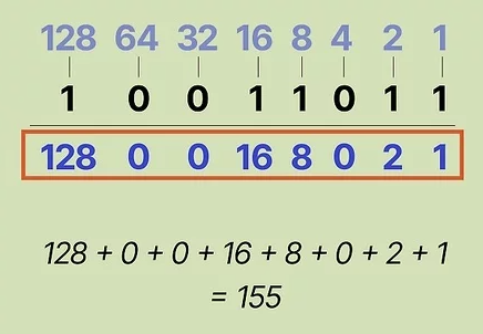
This layer includes the physical equipment involved in the data transfer, such as cables and switches. This is also the layer where the data gets converted into a bit stream, which is a string of 1s and 0s. The physical layer of both devices must also agree on a signal convention so that the 1s can be distinguished from the 0s on both devices.
PS: It's actually possible to convert from binary to decimal. Each position in a binary value corresponds to a specific decimal value. A 1 means that bit is "activated" and can be added to the sum. The sum will equal one octect, if you're talking about an IPv4 address.
How data flows through the OSI Model
In order for human-readable information to be transferred over a network from one device to another, the data must travel down the seven layers of the OSI Model on the sending device and then travel up the seven layers on the receiving end.
For example, if a user wants to send an email, the user composes his email in an email application on his laptop and clicks "send". His email application will pass his email message over to the application layer, which will pick a protocol (SMTP) and pass along the data to the presentation layer. The presentation layer will then compress the data, and then it will hit the session layer, which will initialize the communication session.
The data then hit's the sender's transportation layer where it will be segmented, then those segments will be broken up into packets at the network layer, which will be broken down even further into frames at the data link layer. The data link layer will then deliver those frames to the physical layer, which will convert the data into a bitstream of 1s and 0s and send it through a physical medium, such as a cable.
Once the the recipient's computer receives the bit stream through a physical medium (such as their WiFi), the data will flow through the same series of layers on their device, but in the opposite order. First the physical layer will convert the bitstream from 1s and 0s that get passed down to the data link layer. The data link layer will then reassemble the frames into packets for the network layer. The network layer will then make segments out of the packets for the transport layer, which will reassemble the segments into one piece of data.
The data will then flow into the receiver's session layer, which will pass the data along to the presentation layer and then end the communication session. The presentation layer will then remove the compression and pass the raw data up to the application layer. The application layer will then feed the human-readable data along to the recipient's email software, which will allow them to read the sender's email on their laptop screen.
How the OSI Model is used in network troubleshooting
Because the OSI Model gives you a good idea on how traffic flows through networks, and gives you protocols which are tied exclusively to the functionality of those layers, it provides a good, hierarchical approach to troubleshooting network problems.
When you encounter issues with the network, the ethos is to start from the ground-up. Or, try the easiest, most obvious thing first and work your way up from there. So when there's a network problem, check layer 1 first. Are cables plugged in? Is the WiFi turned on? A lot of network problems reside on layer 1, so it's good to check as a part of your troubleshooting process.
If cables are good, check layer 2. As mentioned before, layer 2 is responsible for flow and error control in intra-network communications. If there is a problem during transmission, you will likely get a lot of retransmissions, showing up as cyclic redundancy check (CRC) errors on a switch's management dashboard or interface configuration page.
If there's a lot of retransmissions, it usually indicates some kind of issue with the physical layer. This could be interference in a wireless, or some kind of problem with Ethernet infrastructure. If there are a multitude of people having issues, it's not impossible for it to be something like this. Maybe an uplink cable is bad, or maybe wireless AP placement is poor, etc.
If layer 1 and 2 are fine, check layer 3. Can you ping the machine's loopback? If not, it may be a bad NIC or some other problem with the device such as a bad driver. Being unable to ping the devices own IP address may also mean a problem with a NIC, but it could mean a firewall issue, if you can ping the loopback but not the IP address. One thing to check in that scenario is if the person has a VPN turned on.
Layer 4 issues are somewhat rare. It's possible a TCP handshake may fail, but typically these are retransmitted. UDP kind of just "yeets" data out there regardless of what form it takes. However, if you find that specifically UDP traffic is being blocked either via a Wireshark session or something, it may be because of an Access Control List (ACL) on a router, L3 switch, or a security gateway or firewall. You have the ability to block protocols from layer 4 via an ACL. So check your ACL rules if you see a pattern of TCP or UDP traffic being blocked.
Layers 5, 6 and 7 are considered the "data stream" of an application. Most often these are treated as one. Troubleshooting usually involves troubleshooting issues with the layer 7 application. (i.e. Outlook is having issues), but rarely you may see layer 5 and 6 problems. You may have a firewall rule which restricts a layer 5 protocol, like SCP, RPC, NetBIOS, etc.
Problems with layer 6 involve data integrity and potentially corruption. Check the data format and encoding of the L7 application, as well as the conversation, compression, encryption, and integrity and validation of the data using something like Wireshark. Data should not be in plaintext. If it is, then something is wrong with layer 6.
It's still important to note that generally speaking, most problems occur at the bottom 4 layers, and sometimes at layer 7, but rarely layers 5 and 6. |

No comments to display
No comments to display